Development Board Overview
ESP32 is the platformin use while nodemcu-32s as the board type.
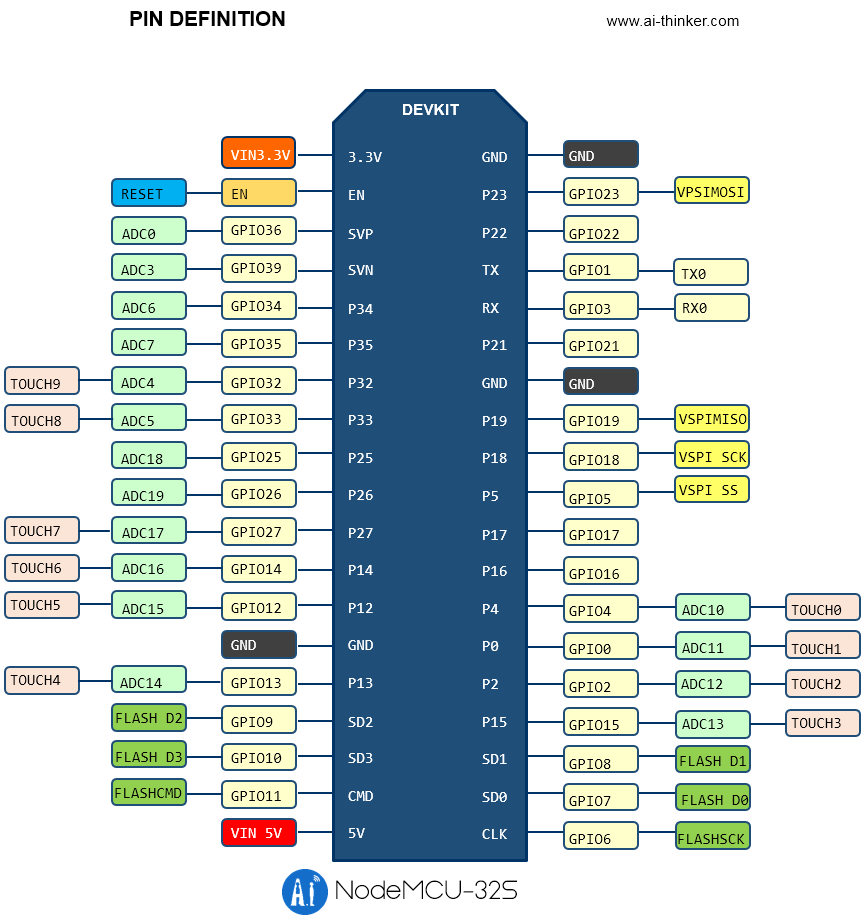
ESP32-DevKit is a small-sized ESP32-based development board produced by Espressif. Most of the I/O pins are broken out to the pin headers on both sides for easy interfacing.
can either connect peripherals with jumper wires or mount ESP32-DevKit on a breadboard
| Key Component | Description |
|---|---|
| ESP32-WROOM-32 | A module with ESP32 at its core. For more information, see ESP32-WROOM-32 Datasheet. |
| EN | Reset button. |
| Boot | Download button. Holding down Boot and then pressing EN initiates Firmware Download mode for downloading firmware through the serial port. |
| >USB-to-UART Bridge | Single USB-UART bridge chip provides transfer rates of up to 3 Mbps. |
| I/O | Most of the pins on the ESP module are broken out to the pin headers on the board. You can program ESP32 to enable multiple functions such as PWM, ADC, DAC, I2C, I2S, SPI, etc. |
| 5V Power On LED | Turns on when the USB or an external 5V power supply is connected to the board. For details see the schematics in Related Documents. |
LED Based Project
Traffic light🚦controller
The traffic light🚦controller is a specially built system that changes the lights on the timer, to help pedestrians who want to cross, and can even adjust the timing of the light depending on the traffic.A traffic light, traffic signal, or stop light is a signaling device positioned at a road intersection, pedestrian crossing, or other location in order to indicate when it is safe to drive, ride, or walk using a universal color code.
In Malaysia, the traffic lights for vehicles commonly have three main lights, a red light that means stop, a green light that mean go and yellow that means ready to stop.
Purpose Traffic light controller
To find the way to maximize the traffic flow smoothly can reduce the numbers of the accident and can reduce the people time in road. The government has carried out a few rules to overcome this problem.Beside take the punishment to all the traffic offenders, the traffic lights have been madeat the location that high risk in accident. This project makes use of LED lights for indication purpose and a microcontroller is used for auto changing of signal at specified range of time interval. LED lights gets automatically turns on and off by making corresponding port pin of the microcontroller “HIGH”.
Traffic Light Project
Traffic light demonstration using LEDs
h4>Analog signals
Analogue inputs are used in control systems with input sensors that produce a voltage, current or resistance change in response to an environmental variation or system measurement and instead of only reading the values of 1 and 0 (on and off),
it can read values in between.The signals from sensors that measure surrounding natural factors such as temperature, pressure, and flow rate are often analog signals, and most control actuators move according to analog signals.
On the other hand, only digital signals can be handled by computers. For this reason, in order to input a signal from a sensor using a computer, or to output a signal to an actuator, it's necessary to have a device that can bridge the analog signal
and the digital signal handled by the computer. That bridge is called an analog I/O interface.
A potentiometer is the perfect analogue device for this activity.Once the potentiometeris turned on the maximum and minimum values are approximately between 0 and 65025.These values are used to control the duty cycle for PWM on the LED.
Analog signals
Analogue inputs are used in control systems with input sensors that produce a voltage, current or resistance change in response to an environmental variation or system measurement and instead of only reading the values of 1 and 0 (on and off),it can read values in between.The signals from sensors that measure surrounding natural factors such as temperature, pressure, and flow rate are often analog signals, and most control actuators move according to analog signals.
On the other hand, only digital signals can be handled by computers. For this reason, in order to input a signal from a sensor using a computer, or to output a signal to an actuator, it's necessary to have a device that can bridge the analog signal
and the digital signal handled by the computer. That bridge is called an analog I/O interface.
A potentiometer is the perfect analogue device for this activity.Once the potentiometeris turned on the maximum and minimum values are approximately between 0 and 65025.These values are used to control the duty cycle for PWM on the LED.
PIR
A passive infrared sensor (PIR sensor) is an electronic sensor that measures infrared (IR) light radiating from objects in its field of view. They are most often used in PIR-based motion detectors. PIR sensors are commonly used in securityalarms and automatic lighting applications. It can detect changes in the amount of infrared radiation impinging upon it, which varies depending on the temperature and surface characteristics of the objects in front of the sensor.
When an object, such as a person, passes in front of the background, such as a wall, the temperature at that point in the sensor's field of view will rise from room temperature to body temperature, and then back again. The sensor converts the resulting
change in the incoming infrared radiation into a change in the output voltage, and this triggers the detection. Objects of similar temperature but different surface characteristics may also have a different infrared emission pattern, and thus moving them
with respect to the background may trigger the detector as well.
You can detect motion with the PIR using the code below:
Ultrasonic Sensor
An ultrasonic distance sensor sends out pulses of ultrasound which are inaudible to humans, and detects the echo that is sent back when the sound bounces off a nearby object. It then uses the speed of sound to calculate the distance from the object.Ultrasonic transducer is energized by high voltage pulses and starts to emit an ultrasonic signal. The ultrasonic signal is reflected by the target towards the sensor.Trigger circuit measures the time between the emission and the detection of the signal.
Since the speed of the ultrasonic beam in air is known, it is easy to have not only an indication of the presence of the target, but also a measure of the distance between sensor and target.
Ultrasonic Sensor Working Principle
Ultrasonic sensors emit short, high-frequency sound pulses at regular intervals. These propagate in the air at the velocity of sound. If they strike an object, then they reflected back as an echo signals to the sensor, which itself computes the distanceto the target based on the time-span between emitting the signal and receiving the echo. An ultrasonic sensors are excellent at suppressing background interference. Virtually all materials which reflect sound can be detected, regardless of their colour.
Even transparent materials or thin foils represent no problem for an ultrasonic sensor. microsonic ultrasonic sensors are suitable for target distances from 20 mm to 10 m and as they measure the time of flight they can ascertain a measurement with pinpoint accuracy.
If you need to measure the specific distance from your sensor, this can be calculated based on this formula: We know that, Distance= Speed* Time.
The speed of sound waves is 343 m/s. So, Total Distance= (343 * Time of hight(Echo) pulse)/2 Total distance is divided by 2 because signal travels from HC-SR04 to object and returns to the module HC-SR-04. Use the following code to read the Distance